论坛回复已创建
-
作者帖子
-
 123参与者
屏幕校正
选取屏幕四个角上的四个点,将读取的数据存放在一个二维数组中,然后根据计算的factor值判定校准是否成功,如果成功则进入下一步,不成功的话就再来一次。触屏校正代码如下所示:
void tp_adjust(void)

{

uint8_t cnt = 0;

uint16_t hwTimeout = 0, d1, d2, pos_temp[4][2];

uint32_t tem1, tem2;

float fac;

lcd_clear_screen(LCD_COLOR_WHITE);

lcd_display_string(40, 40, (const uint8_t *)"Please use the stylus click the cross on the screen. The cross will always move until the screen adjustment is completed.",

16, LCD_COLOR_RED);

tp_draw_touch_point(20, 20, LCD_COLOR_RED);

s_tTouch.chStatus = 0;

s_tTouch.fXfac = 0;

while (1) {

tp_scan(1);

if((s_tTouch.chStatus & 0xC0) == TP_PRESSED) {

hwTimeout = 0;

s_tTouch.chStatus &= ~(1 << 6);

pos_temp[cnt][0] = s_tTouch.hwXpos;

pos_temp[cnt][1] = s_tTouch.hwYpos;

cnt ++;

switch(cnt) {

case 1:

tp_draw_touch_point(20, 20, LCD_COLOR_WHITE);

tp_draw_touch_point(LCD_WIDTH - 20, 20, LCD_COLOR_RED);

break;

case 2:

tp_draw_touch_point(LCD_WIDTH - 20, 20, LCD_COLOR_WHITE);

tp_draw_touch_point(20, LCD_HEIGHT - 20, LCD_COLOR_RED);

break;

case 3:

tp_draw_touch_point(20, LCD_HEIGHT - 20, LCD_COLOR_WHITE);

tp_draw_touch_point(LCD_WIDTH - 20, LCD_HEIGHT - 20, LCD_COLOR_RED);

break;

case 4:

tem1=abs((int16_t)(pos_temp[0][0]-pos_temp[1][0]));//x1-x2

tem2=abs((int16_t)(pos_temp[0][1]-pos_temp[1][1]));//y1-y2

tem1*=tem1;

tem2*=tem2;

tem1+=tem2;

d1=sqrt(tem1);

tem1=abs((int16_t)(pos_temp[2][0]-pos_temp[3][0]));//x3-x4

tem2=abs((int16_t)(pos_temp[2][1]-pos_temp[3][1]));//y3-y4

tem1*=tem1;

tem2*=tem2;

tem1+=tem2;

d2=sqrt(tem1);

fac=(float)d1/d2;

if(fac<0.95||fac>1.05||d1==0||d2==0) {

cnt=0;

tp_show_info(pos_temp[0][0],pos_temp[0][1],pos_temp[1][0],pos_temp[1][1],pos_temp[2][0],pos_temp[2][1],pos_temp[3][0],pos_temp[3][1],fac*100);

lcd_delayms(1000);

tp_draw_touch_point(LCD_WIDTH - 20, LCD_HEIGHT - 20, LCD_COLOR_WHITE);

tp_draw_touch_point(20, 20, LCD_COLOR_RED);

continue;

}

tem1=abs((int16_t)(pos_temp[0][0]-pos_temp[2][0]));//x1-x3

tem2=abs((int16_t)(pos_temp[0][1]-pos_temp[2][1]));//y1-y3

tem1*=tem1;

tem2*=tem2;

tem1+=tem2;

d1=sqrt(tem1);

tem1=abs((int16_t)(pos_temp[1][0]-pos_temp[3][0]));//x2-x4

tem2=abs((int16_t)(pos_temp[1][1]-pos_temp[3][1]));//y2-y4

tem1*=tem1;

tem2*=tem2;

tem1+=tem2;

d2=sqrt(tem1);

fac=(float)d1/d2;

if(fac<0.95||fac>1.05) {

cnt=0;

tp_show_info(pos_temp[0][0],pos_temp[0][1],pos_temp[1][0],pos_temp[1][1],pos_temp[2][0],pos_temp[2][1],pos_temp[3][0],pos_temp[3][1],fac*100);

lcd_delayms(1000);

lcd_fill_rect(96, 240, 24, 16, LCD_COLOR_WHITE);

tp_draw_touch_point(LCD_WIDTH - 20, LCD_HEIGHT - 20, LCD_COLOR_WHITE);

tp_draw_touch_point(20, 20, LCD_COLOR_RED);

continue;

}

tem1=abs((int16_t)(pos_temp[1][0]-pos_temp[2][0]));//x2-x3

tem2=abs((int16_t)(pos_temp[1][1]-pos_temp[2][1]));//y2-y3

tem1*=tem1;

tem2*=tem2;

tem1+=tem2;

d1=sqrt(tem1);

tem1=abs((int16_t)(pos_temp[0][0]-pos_temp[3][0]));//x1-x4

tem2=abs((int16_t)(pos_temp[0][1]-pos_temp[3][1]));//y1-y4

tem1*=tem1;

tem2*=tem2;

tem1+=tem2;

d2=sqrt(tem1);

fac=(float)d1/d2;

if(fac<0.95||fac>1.05) {

cnt=0; tp_show_info(pos_temp[0][0],pos_temp[0][1],pos_temp[1][0],pos_temp[1][1],pos_temp[2][0],pos_temp[2][1],pos_temp[3][0],pos_temp[3][1],fac*100);

lcd_delayms(1000);

tp_draw_touch_point(LCD_WIDTH - 20, LCD_HEIGHT - 20, LCD_COLOR_WHITE);

tp_draw_touch_point(20, 20, LCD_COLOR_RED);

continue;

}

s_tTouch.fXfac = (float)(LCD_WIDTH - 40) / (int16_t)(pos_temp[1][0] - pos_temp[0][0]);

s_tTouch.iXoff = (LCD_WIDTH - s_tTouch.fXfac * (pos_temp[1][0] + pos_temp[0][0])) / 2;

s_tTouch.fYfac = (float)(LCD_HEIGHT - 40) / (int16_t)(pos_temp[2][1] - pos_temp[0][1]);

s_tTouch.iYoff = (LCD_HEIGHT - s_tTouch.fYfac * (pos_temp[2][1] + pos_temp[0][1])) / 2;

if(abs(s_tTouch.fXfac) > 2 || abs(s_tTouch.fYfac) > 2) {

cnt=0;

tp_draw_touch_point(LCD_WIDTH - 20, LCD_HEIGHT - 20, LCD_COLOR_WHITE);

tp_draw_touch_point(20, 20, LCD_COLOR_RED);

lcd_display_string(40, 26, (const uint8_t *)"TP Need readjust!", 16, LCD_COLOR_RED);

continue;

}

lcd_clear_screen(LCD_COLOR_WHITE);

lcd_display_string(35, 110, (const uint8_t *)"Touch Screen Adjust OK!", 16, LCD_COLOR_BLUE);

lcd_delayms(1000);

lcd_clear_screen(LCD_COLOR_WHITE);

return;

}

}

lcd_delayms(600);

if (++ hwTimeout >= 6000) {

break;

}

}

}
其中调用到tp_scan()函数,检测是否有触屏并获得物理坐标值,具体实现如下:
uint8_t tp_scan(uint8_t chCoordType)

{

if (!(XPT2046_IRQ_READ())) {

if (chCoordType) {

xpt2046_twice_read_xy(&s_tTouch.hwXpos, &s_tTouch.hwYpos);

} else if (xpt2046_twice_read_xy(&s_tTouch.hwXpos, &s_tTouch.hwYpos)) {

s_tTouch.hwXpos = s_tTouch.fXfac * s_tTouch.hwXpos + s_tTouch.iXoff;

s_tTouch.hwYpos = s_tTouch.fYfac * s_tTouch.hwYpos + s_tTouch.iYoff;

}

if (0 == (s_tTouch.chStatus & TP_PRESS_DOWN)) {

s_tTouch.chStatus = TP_PRESS_DOWN | TP_PRESSED;

s_tTouch.hwXpos0 = s_tTouch.hwXpos;

s_tTouch.hwYpos0 = s_tTouch.hwYpos;

}

} else {

if (s_tTouch.chStatus & TP_PRESS_DOWN) {

s_tTouch.chStatus &= ~(1 << 7);

} else {

s_tTouch.hwXpos0 = 0;

s_tTouch.hwYpos0 = 0;

s_tTouch.hwXpos = 0xffff;

s_tTouch.hwYpos = 0xffff;

}

}

return (s_tTouch.chStatus & TP_PRESS_DOWN);

}
触屏效果
最终,实现可以在屏幕上实现绘画和简单的清屏对话
最后展示一下我的简笔画兔子(嘻嘻):
本帖的部分内容参考了XPT2046触摸屏实验过程详解与STM32代码解析和2.8inch TFT Touch Shield用户手册
 123参与者
代码的补充和优化
优化
以单个像素点来读取数据可能会有点慢,一次读取多个像素点能大大提高读取速度,但也有一些情况就是需要一次只读取一个像素点,所以我定义了一个宏HIGH_LEVEL_OPTIMIZE,来控制选择是否一次读取多个像素点:
#if HIGH_LEVEL_OPTIMIZE

static uint16_t LCD_MULTI_WORD_WRITE(uint16_t* data, uint16_t len)

{

uint8_t *transfer = (uint8_t*)malloc(len);

lpspi_transfer_t masterXfer;

if(transfer){

uint8_t exist = len % 8; //copy 8 Byte one time

uint32_t i = 0;

for(;i<(len - exist);){ transfer[i++] = (*(data)) & 0xff; transfer[i++] = ((*(data++)) & 0xff00) >> 8;

transfer[i++] = (*(data)) & 0xff;

transfer[i++] = ((*(data++)) & 0xff00) >> 8;

transfer[i++] = (*(data)) & 0xff;

transfer[i++] = ((*(data++)) & 0xff00) >> 8;

transfer[i++] = (*(data)) & 0xff;

transfer[i++] = ((*(data++)) & 0xff00) >> 8;

}

for(int j=0;j<exist/2;j++){ transfer[i++] = (*(data)) & 0xff; transfer[i++] = ((*(data++)) & 0xff00) >> 8;

}

masterXfer.txData = transfer;

masterXfer.rxData = NULL;

masterXfer.dataSize = len;

masterXfer.configFlags = BOARD_LPSPI_PCS_FOR_TRANSFER | kLPSPI_MasterPcsContinuous;

LPSPI_MasterTransferBlocking(LCD_SPI, &masterXfer);

free(transfer);

transfer = NULL;

}

else{

free(transfer);

transfer = NULL;

return -1;

}

return *data;

}

#endif
修改lcd_clear_screen(uint16_t color)函数,代码如下:
void lcd_clear_screen(uint16_t color)

{

uint32_t i, cnt = 0;

cnt = LCD_WIDTH * LCD_HEIGHT;

lcd_set_cursor(0, 0);

lcd_write_byte(0x22, LCD_CMD);

LCD_DC_SET();

#if HIGH_LEVEL_OPTIMIZE

const uint32_t nPixelSet = 32; //send n pixels one time

uint16_t temp[nPixelSet];

uint16_t color2send = INVERSE_MSB(color); //MSB first, need to convert the data

for(int i=0;i<nPixelSet;){

temp[i++] = color2send;

temp[i++] = color2send;

temp[i++] = color2send;

temp[i++] = color2send;

}

/*** Send 64 Bytes one time, but the lcd will accept one 16-bit as a pixel,

so the len will be the len of the (uint16), need to sizeof(temp)/sizeof(uint16_t);***/

for (i = 0; i < cnt; i += nPixelSet)

{

LCD_MULTI_WORD_WRITE(temp, sizeof(temp));

}

#else

/**** send 2 bytes one time***/

for (i = 0; i < cnt; i ++)

{

LCD_WORD_WRITE(color);

}

#endif

}
显示图片部分的代码也是通过类似的方法来优化。
补充
一楼显示的配置SPI的代码看起来有点乱,我想修改的时候已经不能编辑了,在这里重新写一遍:
static uint8_t lcd_hardware_init(void)

{

lpspi_master_config_t masterConfig;

uint32_t srcClock_Hz;

/* SPI init */

LPSPI_MasterGetDefaultConfig(&masterConfig);

/*********Master config*********/

masterConfig.baudRate = 24000000;

/* 这里LPSPI_TRANSFER_SIZE的值在宏定义中设置为1 */

masterConfig.bitsPerFrame = 8*LPSPI_TRANSFER_SIZE;

masterConfig.cpol = kLPSPI_ClockPolarityActiveHigh;

masterConfig.cpha = kLPSPI_ClockPhaseFirstEdge;

masterConfig.direction = kLPSPI_MsbFirst;

masterConfig.pcsToSckDelayInNanoSec = 1000000000 / masterConfig.baudRate;

masterConfig.lastSckToPcsDelayInNanoSec = 1000000000 / masterConfig.baudRate;

masterConfig.betweenTransferDelayInNanoSec = 1000000000 / masterConfig.baudRate;

/* 设置pcs2为片选信号 */

masterConfig.whichPcs = kLPSPI_Pcs2;

masterConfig.pcsActiveHighOrLow = kLPSPI_PcsActiveLow;

masterConfig.pinCfg = kLPSPI_SdiInSdoOut;

masterConfig.dataOutConfig = kLpspiDataOutRetained;

srcClock_Hz = CLOCK_GetIpFreq(kCLOCK_Lpspi0);

LPSPI_MasterInit(LCD_SPI, &masterConfig, srcClock_Hz);

return true;

} 123参与者
添加显示图片代码
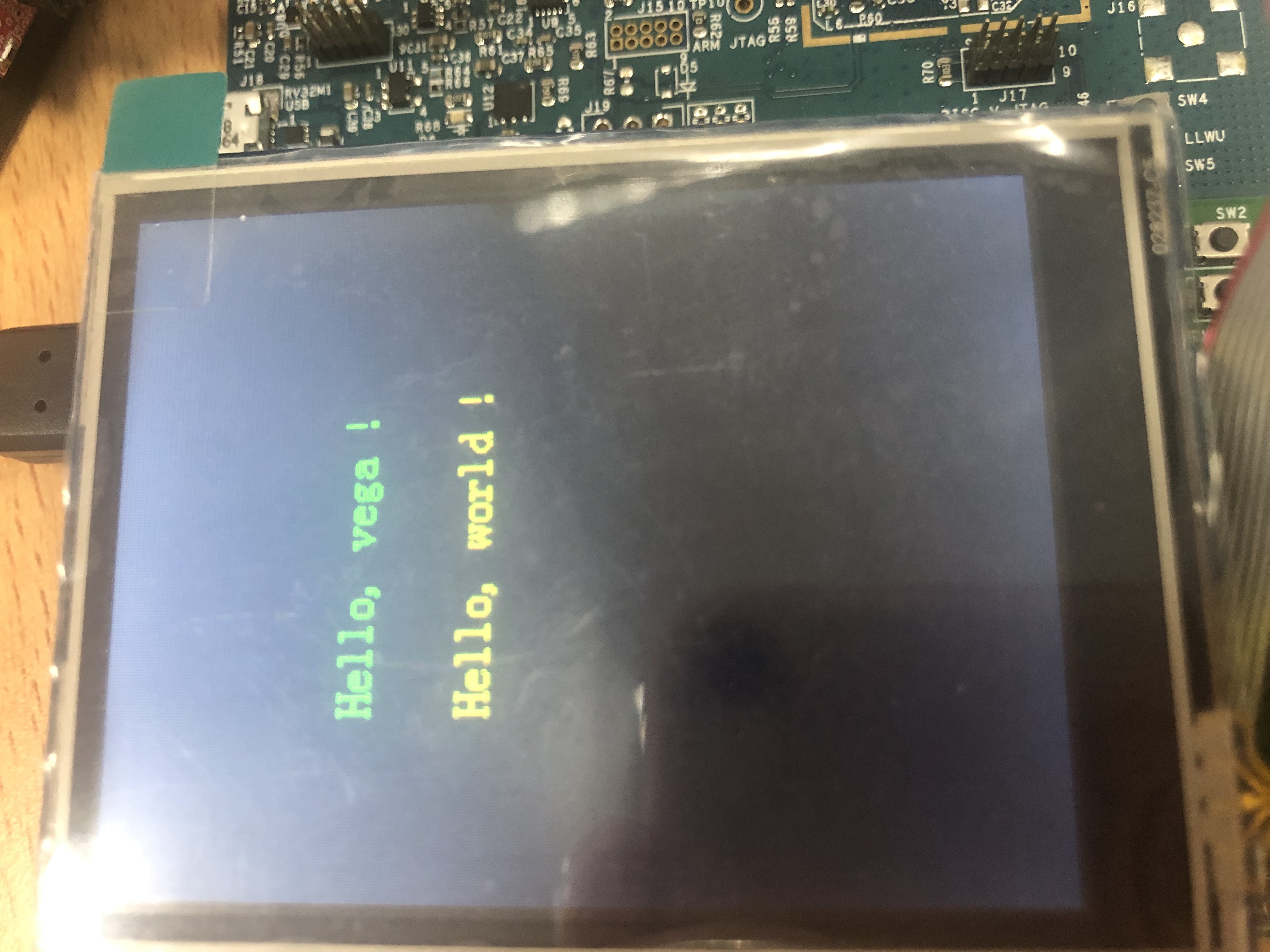
前面提到的那个Arduino LCD模块的网页里有图片提取软件,先利用这个工具把图片转换成16位的彩色数据,生成一个大数组的C文件,把这个数组复制到 lcd_fonts文件中,再在主函数中调用就可以了。
根据屏幕刷新的部分改写了个显示图片的代码:
void lcd_showimage(const unsigned char *p)

{

uint32_t i, cnt = 0;

uint16_t data;

uint8_t d1,d2;

cnt = LCD_WIDTH * LCD_HEIGHT ;

lcd_set_cursor(0, 0);

lcd_write_byte(0x22, LCD_CMD);

LCD_DC_SET();

for (i = 0; i < cnt; i ++)

{

d1 = *p++;

d2 = *p++;

data = (uint16_t)d1+((uint16_t)d2<<8);

LCD_WORD_WRITE(data);

}

}
展示一下最终的成果: 123参与者
好哒,谢谢你!
 123参与者
 -
作者帖子


